
When Cyclone Gabrielle dumped more than 400mm of rain on parts of Hawke’s Bay in February 2023, it wasn’t the volume of water sitting on the surface that triggered thousands of slope failures across the region. It was the water nobody could see, rising silently within the soil mass, stripping away the effective stress that held hillsides together. In New Zealand, elevated pore water pressure following intense rainfall is the single dominant trigger of slope instability, and subsurface drainage remains our most powerful, most underutilised tool for managing it.
Too often, drainage is treated as an afterthought bolted onto a retaining wall design at the last minute. At Chambers Consultants, we see this as a fundamental misreading of how slopes actually fail. Good slope-drainage-design isn’t a supplementary measure — it is frequently the primary line of defence, and in many cases it is more cost-effective than structural reinforcement alone.
Why Pore Pressure Is the Real Enemy
Slope stability is governed by effective stress: the strength of soil depends on the difference between total stress and pore water pressure. When intense rainfall infiltrates a hillside faster than it can drain, pore pressures rise, effective stress drops, and shear strength along potential failure surfaces falls with it. A slope that has stood for decades at a factor of safety comfortably above 1.5 can drop below 1.0 within hours during a high-intensity storm.
New Zealand’s combination of steep topography, weathered greywacke, volcanic ash soils, and increasingly intense rainfall events (NIWA data shows a clear trend toward more frequent high-intensity short-duration storms under a warming climate) makes this mechanism particularly acute. GNS Science’s post-Gabrielle landslide mapping identified over 10,000 individual slope failures across the North Island, the overwhelming majority triggered by rapid pore pressure buildup rather than erosion or loading.
The implication for engineers and asset owners is clear: if you cannot control the water, you cannot reliably control the slope. Subsurface drainage systems — cut-off drains, counterfort drains, and weep holes — are designed specifically to intercept, collect, and safely remove that water before it compromises stability.
The Three Lines of Defence
Cut-off Drains: Intercepting Water Before It Arrives
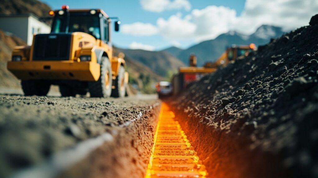
Cut-off drains (also called interceptor drains) are installed upslope of the area requiring protection, typically as trenches backfilled with free-draining aggregate wrapped in a geotextile filter, containing a perforated pipe at the invert. Their purpose is straightforward: intercept subsurface seepage and shallow groundwater flow before it reaches the critical slope mass, redirecting it to a safe discharge point.
For residential and infrastructure sites across the Auckland, Wellington and Hamilton regions, we typically design cut-off drains founded on a low-permeability stratum or bedrock, extending 0.5 to 1.0 metres below the anticipated seepage horizon. Pipe sizing is driven by catchment analysis using regional council hydrology guidance, commonly sized to convey the 1% Annual Exceedance Probability (AEP) event with freeboard, consistent with the approach required under most regional and district plan stormwater provisions.
Counterfort Drains: Draining the Slope From Within
Where instability is driven by perched groundwater or elevated piezometric levels within the slope itself, counterfort drains do the heavier lifting. These are near-vertical trenches excavated into the slope, typically 600mm to 1000mm wide, spaced at 3 to 6 metre centres perpendicular to the slope contour, backfilled with free-draining granular material and a perforated collector pipe. Beyond their hydraulic function, counterfort drains also provide a buttressing effect, replacing weak soil with a column of high-strength granular fill that increases shear resistance across the potential failure surface.
Spacing and depth are not arbitrary. They should be derived from seepage analysis (commonly using finite element software such as SEEP/W or SLIDE coupled with stability modelling) to confirm the target reduction in piezometric head genuinely achieves the required factor of safety, typically 1.5 for static long-term conditions and 1.2 to 1.3 for rapid drawdown or seismic cases under NZGS and MBIE guidance.
Weep Holes: The Final Relief Valve
For retaining structures, weep holes provide a direct, low-cost pressure relief mechanism, allowing water that accumulates behind a wall to escape before hydrostatic pressure builds to dangerous levels. Typically 50mm to 100mm diameter PVC pipes spaced at 1 to 2 metre centres both horizontally and vertically, weep holes are only as effective as the drainage layer feeding them. Without a properly graded filter zone behind the wall, weep holes clog with fines within a few wet seasons and become ornamental rather than functional.
Designing to New Zealand Standards
Subsurface drainage design in New Zealand sits at the intersection of several frameworks. NZS 4404 informs stormwater and earthworks infrastructure requirements for subdivisions, while geotechnical investigation and reporting should follow NZGS guidelines and align with the performance requirements of NZS 1170.5 for seismic loading where drainage interacts with retaining structures. AS/NZS 1547 and regional trade waste or stormwater bylaws govern discharge points, and most regional councils now require demonstration that subsurface discharge will not exacerbate downstream erosion or flooding, particularly post-Gabrielle where consent authorities have sharpened scrutiny of cumulative catchment effects.
Filter design deserves particular attention. Geotextile and aggregate filter criteria must be matched to the in-situ soil gradation to prevent piping of fines while maintaining hydraulic conductivity. A filter that is too coarse allows migration of fines and progressive clogging; one that is too fine restricts flow and defeats the purpose of the drain entirely. We routinely see failures in the field traced back to generic filter specifications applied without site-specific particle size analysis.
As one senior geotechnical engineer at a major NZ consultancy put it following the 2023 events: “The slopes that failed weren’t necessarily the steepest or the weakest — they were the ones where nobody had asked where the water was going to go.” That observation captures the core discipline of effective slope-drainage-design: it is as much about hydrology and long-term maintenance planning as it is about geotechnical strength parameters.
Key Takeaways From Recent New Zealand Experience
- Design for the real storm, not the historic one. Post-Gabrielle rainfall intensity data now routinely exceeds historic IDC (intensity-duration-frequency) curves in parts of the North Island; drainage systems designed to outdated rainfall records are already under-capacity.
- Counterfort drains outperform surface works alone. Case studies from Wellington’s hill suburbs show slopes retrofitted with counterfort drainage achieving factor of safety improvements of 0.2 to 0.4 — often the margin between a stable slope and a consented one.
- Maintenance is part of the design life. Weep holes and collector pipes silt up. A drainage system without a maintenance and inspection schedule should be treated as a temporary measure, not a permanent solution.
- Filter specification is not generic. Matching geotextile and aggregate selection to site-specific soil gradation prevents the two most common failure modes: piping and clogging.
- Combine structural and hydraulic design early. Retaining wall and drainage design developed in isolation consistently underperform compared with integrated solutions where piezometric reduction targets inform wall geometry from the outset.
Where Drainage Design Commonly Falls Short
In our post-event assessments across the North Island, three recurring issues stand out. First, outlet points are frequently undersized or poorly maintained, leading to backwater effects that defeat the entire system during peak storm events. Second, drains are installed without reference to the actual failure surface identified through slope stability analysis, meaning they intercept water above or below the critical zone rather than within it. Third, and most common, drainage is value-engineered out during construction when budgets tighten, on the assumption that it is a secondary rather than primary stability measure.
Each of these is avoidable with upfront investment in proper site investigation, seepage modelling, and a maintenance commitment from the asset owner. The cost of a well-designed counterfort drain system is almost always a fraction of the cost of remediating a failed slope, let alone the liability exposure that follows a failure affecting adjoining property or infrastructure.
Talk to Chambers Consultants
If your site has a history of seepage, a slope approaching the end of its design life, or sits within a catchment that experienced elevated rainfall during recent storm events, now is the time for a proactive assessment. Chambers Consultants provides integrated geotechnical investigation, seepage analysis, and slope-drainage-design services across New Zealand, calibrated to current rainfall intensity data and regional consenting requirements. Contact our team to discuss a site-specific stability and drainage assessment before the next storm season tests your slope for you.